The flow of charges in a conducting wire is referred to as electric current. Numerically, it is equal to the net charge passing through the wire in one second. The voltage drop (or potential difference) across a section of the wire produces the force required to push the charges and generate the current. Thus, increasing the voltage drop generates more current through the wire.
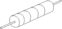
The ability to control currents and voltages in different sections of an electric circuit has many practical applications. A common element of electrical circuits is the resistor (see Figure 2.1), which is available in various resistance values and power-dissipation ratings. Resistors have a resistive material inside them and are often coded with colour bands to indicate resistance value. For many conductors, over a wide range of conditions, the current is directly proportional to the voltage drop. Resistors made of such conductors are called ohmic resistors because they follow Ohm’s law, while those that do not are nonohmic. In the first part of this experiment, you will investigate the relationship between electric potential and current for an ohmic resistor.
A piece of conducting wire also has resistance. However, wires used for connecting different components of an electric circuit are usually made from highly conductive material, such as copper. Therefore, the resistance of these wires can be ignored for most practical purposes. Wires made from material with relatively low conductivity can have significant resistance to the flowing current. For example, the resistance of a piece of Nichrome wire is much larger than the resistance of a similar piece made from copper. In the second part of this experiment, you will explore the relation between the resistance of a Nichrome conducting wire and its length.