Experiment 2 Ohm's Law and Resistivity
This experiment consists of two parts. In the first part, you are to test Ohm's law using a standard resistor. In the second part, you will examine the relation between length and the resistance of a conducting wire.
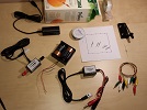
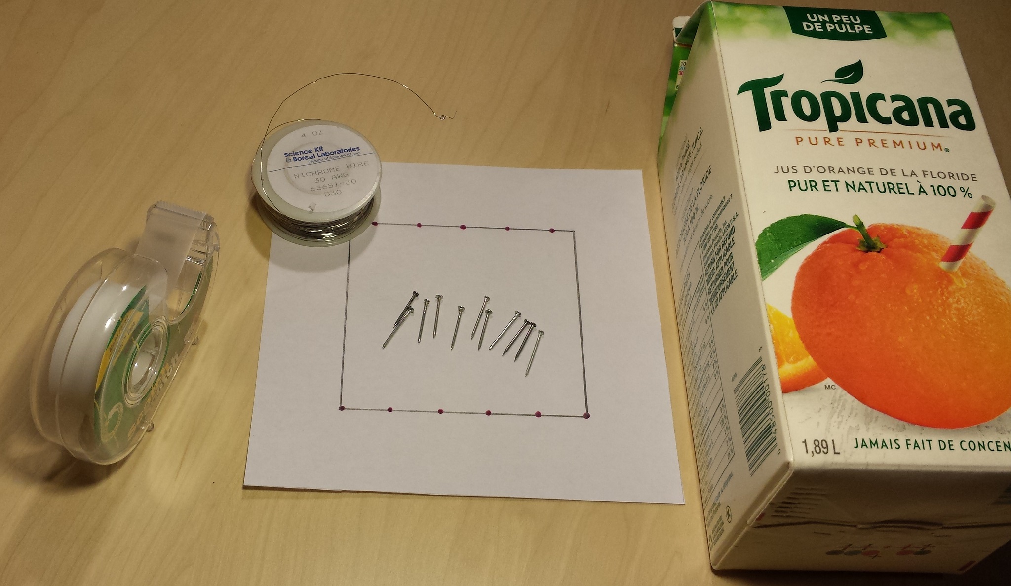
Note that the same setup is used in both parts. For this experiment, you will need the following items, which should be included in the lab kit:
For the purpose of data collection you will need a personal (desktop or laptop) computer that has the Logger Pro software installed on it. The computer is also necessary for data analysis and for the preparation of the lab report.
Before you begin, review the whole procedure to make sure you understand all the steps involved. Perform proper risk assessment and do not proceed with the experiment if you feel that the procedure, equipment, or material pose any safety issues. Remember that safety comes first, and you must always ensure the safety of yourself and any one else at your location. If you have any questions or concerns, please contact your tutor.
In the first part of this experiment, you are to construct the circuit shown in Figure 2.2 and generate a set of data corresponding to the voltage drop across the resistor versus the current flowing in the circuit. Note that the amount of current in the circuit is varied by changing the location of the movable connection on the Nichrome wire.
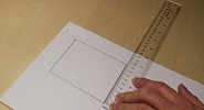
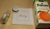
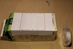
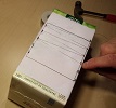
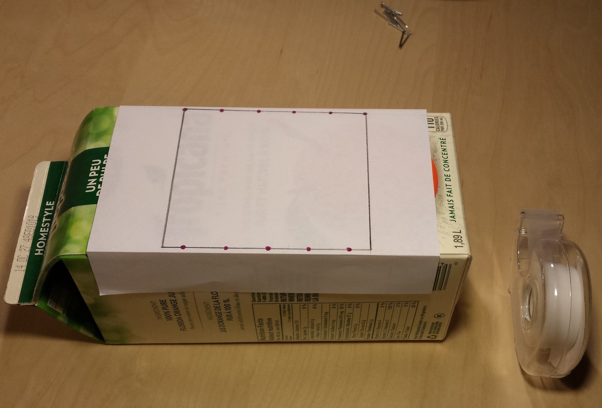
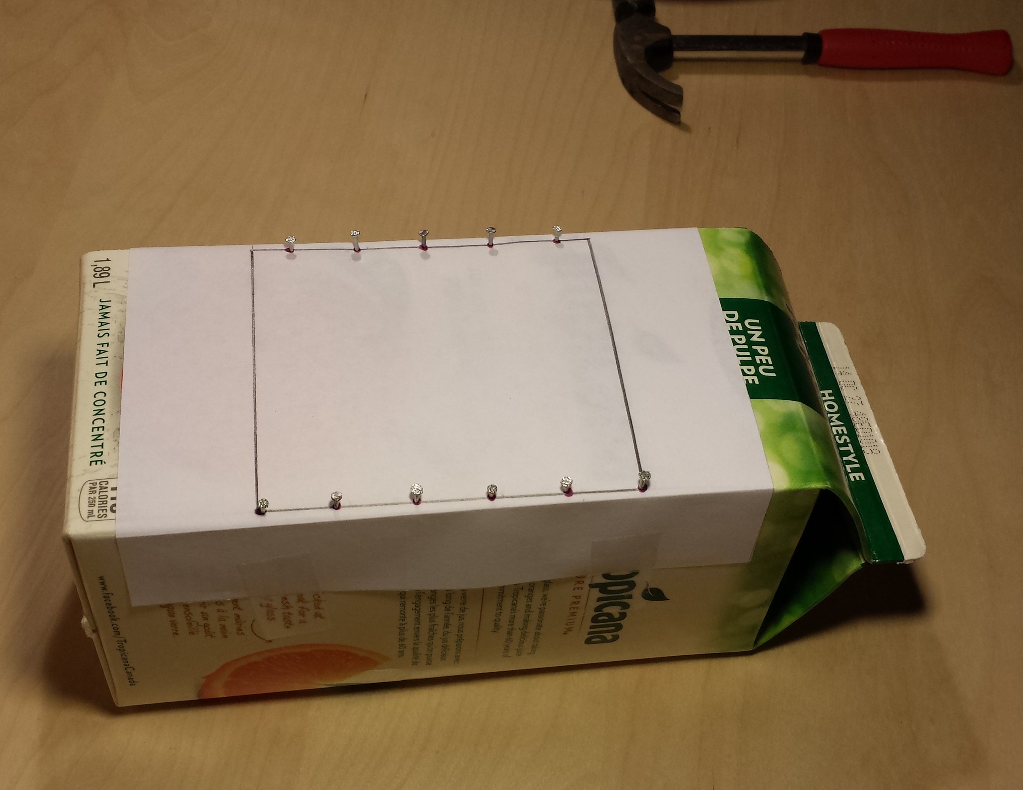
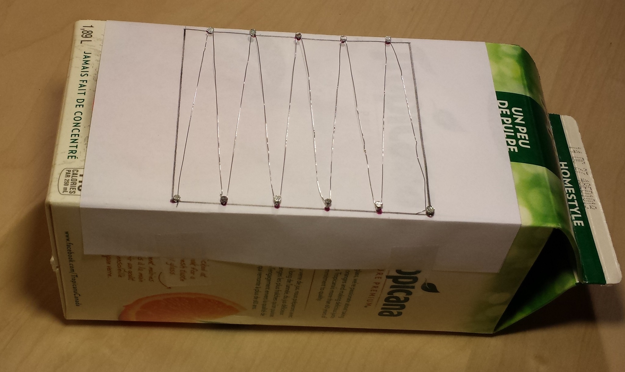
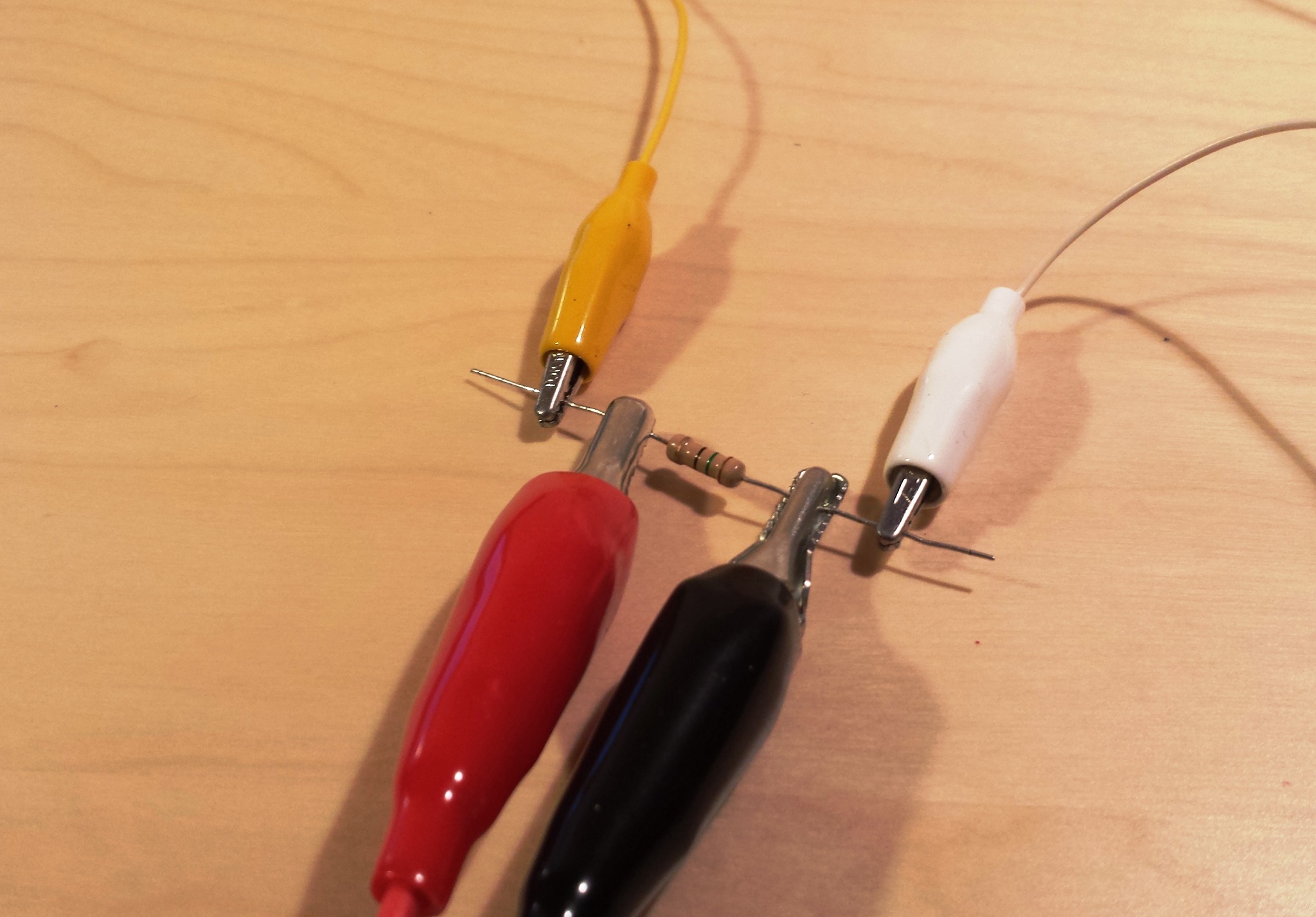
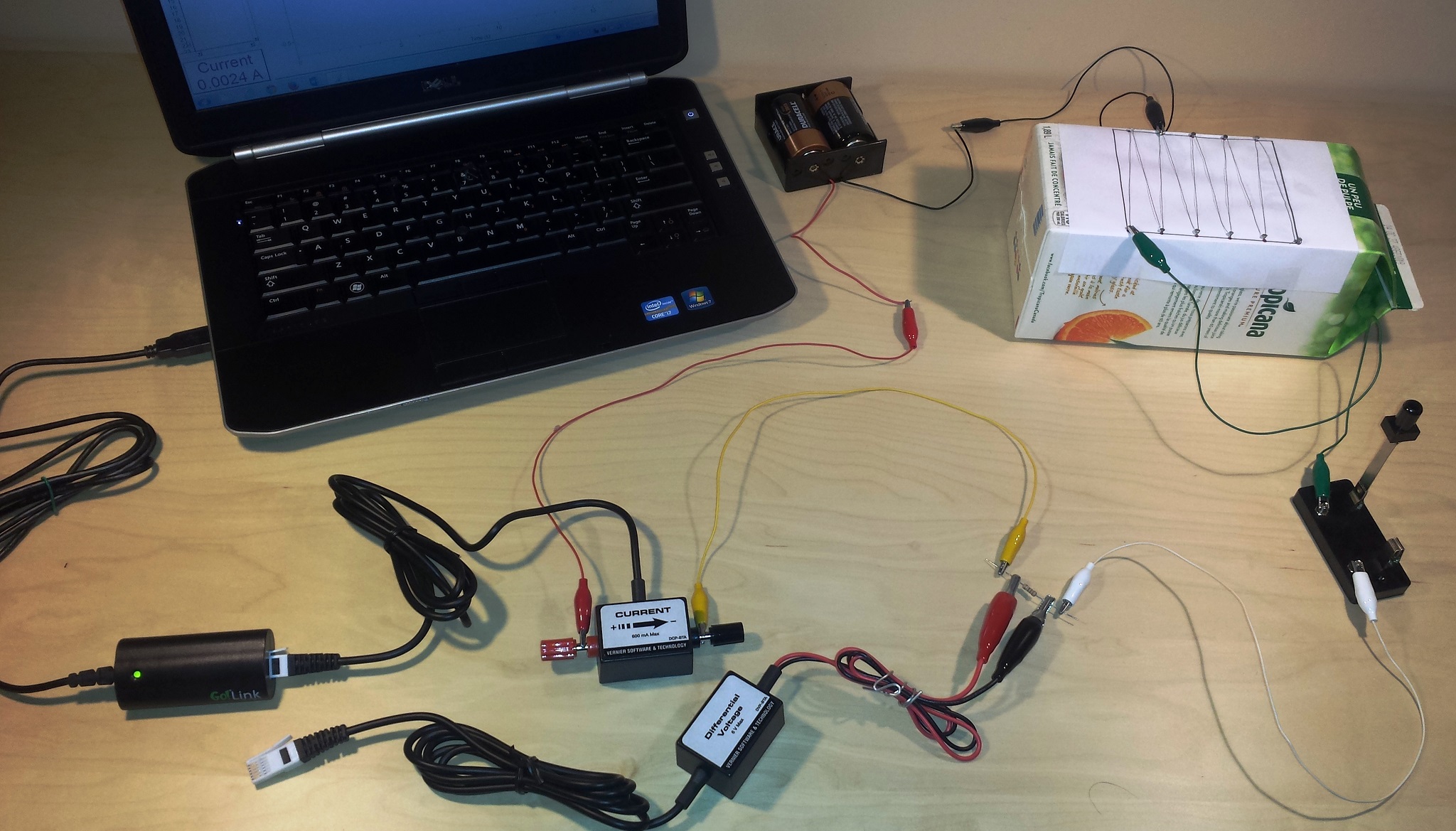
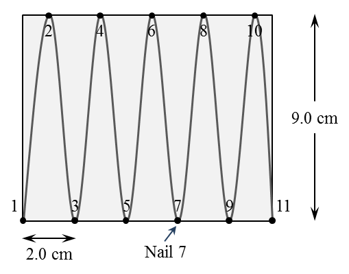
Start the setup by constructing the Nichrome wire component. For this purpose, you need a 2-L juice (or milk) box. Make sure that it is empty and dry before you begin. On a white piece of paper draw and cut a rectangle that can fit on your box (a $10~\text{cm}\times 9.0~\text{cm}$ rectangle should be suitable for a standard 2-L juice container). Make a total of eleven equally spaced marks on the two longer sides of the rectangle, as in Figure 2.2, and tape the paper to the box. Insert a nail halfway through each of these marks. Tie one end of the Nichrome wire to Nail 1. Extend the wire to go around Nail 2, then Nail 3, and so on, until you reach Nail 11. When you feel that the wire is properly stretched (making nearly straight lines between the nails) tie it to Nail 11 and trip any extra. At this point, use the Pythagorean theorem to calculate the distance between two consecutive nails, and write it down. Using the connection cables, assemble the circuit shown in Figure 2.3 with the movable connection attached to Nail 1. See {\sff Lab1-Video} for a demonstration of the experimental setup.
To prevent excessive heating of the Nichrome wire, do not use a power source greater than $3.0\,\text{V}$, and make sure the resistor value is in the range $10$ to $20\,\Omega$. Also, the switch should be left open when measurements are not being made.
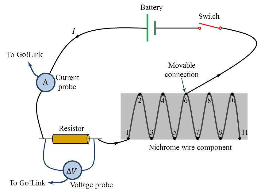
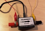
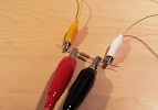
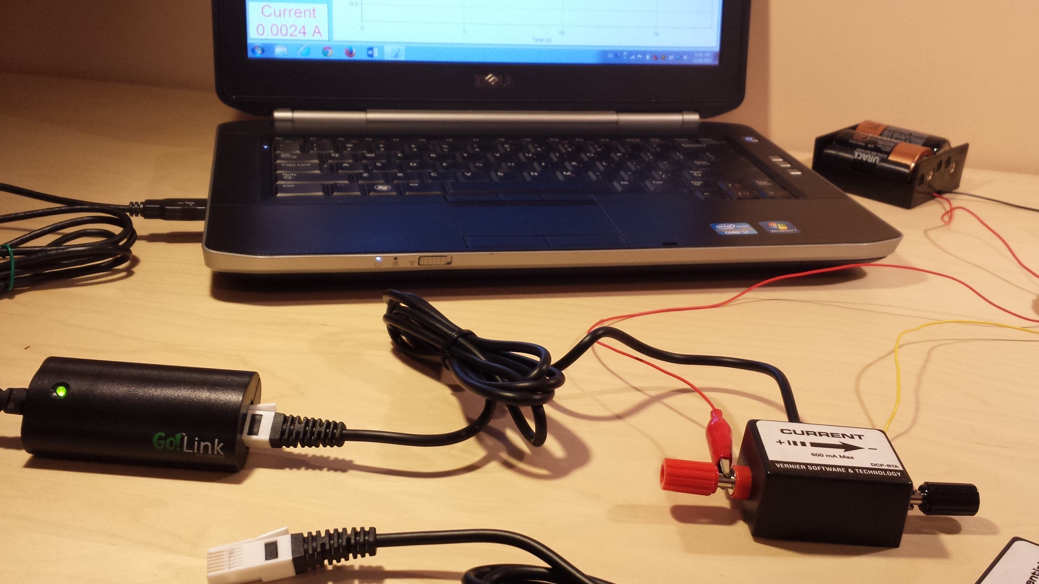
Connect one end of the Go!Link cable to a USB port on your computer and the other end to the Current Probe device. Launch the Logger Pro program. You should see a small window on your computer, displaying the value of the current flowing in the circuit. Since the switch is still open, this value should be close to zero. If it is not, click on Experiment in the menu bar and select Zero... from the scroll down menu. Disconnect the Current Probe from Go!Link and connect the Voltage Probe instead. Again, you should see a small window on your computer, displaying the value of the voltage drop (or potential difference) across the resistor. Here also, you may need to reset the voltage reading to zero.
Close the switch, allowing current to flow in the circuit. Record the value measured by the Voltage Probe in the first row of Table 2.1. Disconnect the Voltage Probe from Go!Link and connect the Current Probe instead. Record the corresponding current value in the table. Remove the movable connection from Nail 1 and attach it to Nail 2. Record the current and voltage values for this situation in the second row of Table 2.1. Continue the process until you reach Nail 11. When you complete your measurements, open the switch to save the battery. Do not forget to take pictures of your setup to include in the lab report.
| Nail | Voltage $\Delta\,V\;(\text{V})$ |
Current ($\text{A}$) |
| 1 | ||
| 2 | ||
| 3 | ||
| 4 | ||
| 5 | ||
| 6 | ||
| 7 | ||
| 8 | ||
| 9 | ||
| 10 |
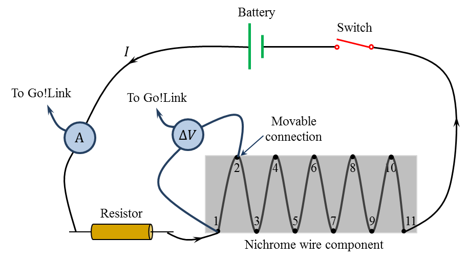
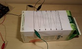
After completing your measurements in Part I, disconnect the Voltage Probe and reconnect it between Nail 1 and Nail 2, as shown in Figure 2.4. While the switch is still open, reset the current and voltage readings to zero. Then, close the switch and record the value of the current flowing in the circuit. There will be no need to make additional current measurements in the remainder of this experiment.
Connect the Voltage Probe to Go!Link, and record the voltage value in the appropriate box in Table 2.2. This value represents the potential difference across the section of the nichrome wire extending between Nail 1 and Nail 2. Do not remove the Voltage~probe terminal from Nail~1 until the end of the experiment. To take the next measurement, move the other terminal from Nail 2 to Nail 3. The voltage value in this case represents the potential difference across the section of the nichrome wire extending between Nail 1 and Nail 3. Continue your measurements by connecting the movable terminal, of the Voltage Probe, to Nail 4, Nail 5, etc., until you reach Nail 11. After recording your data in Table 2.2, open the switch and disconnect your circuit. Take pictures of your setup to include them in the lab report.