Experiment 4 Magnetic Field of a Solenoid
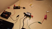
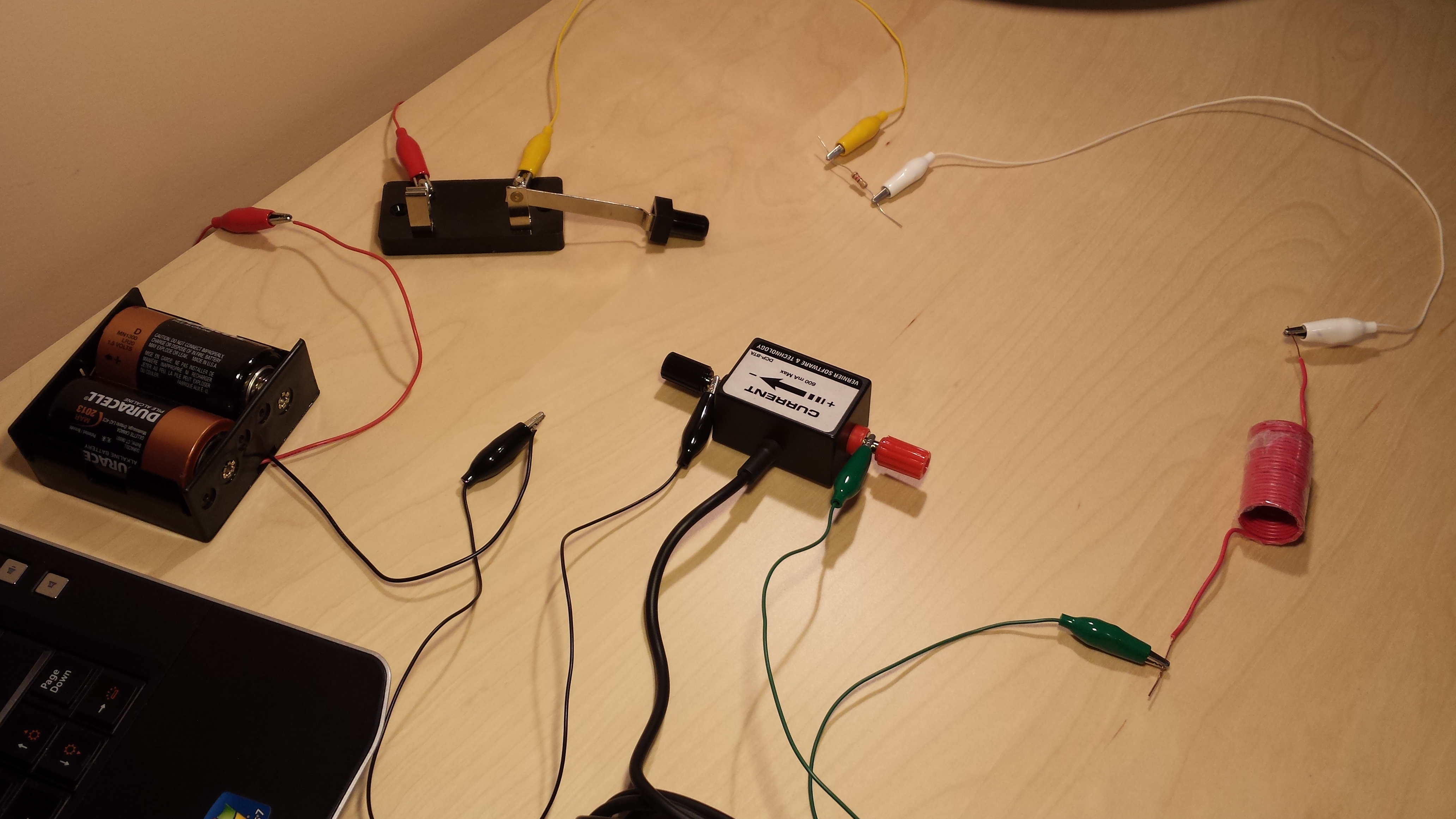
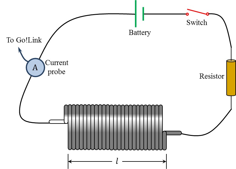
In this experiment you are to construct a solenoid and connect it to a circuit, as shown in Figure 4.2. You will also determine the strength of the magnetic field inside a solenoid using a magnetic sensor. Your experimental measurements of magnetic field versus current should allow you to estimate the value of the magnetic permeability of free space ($\mu_0$).
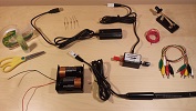
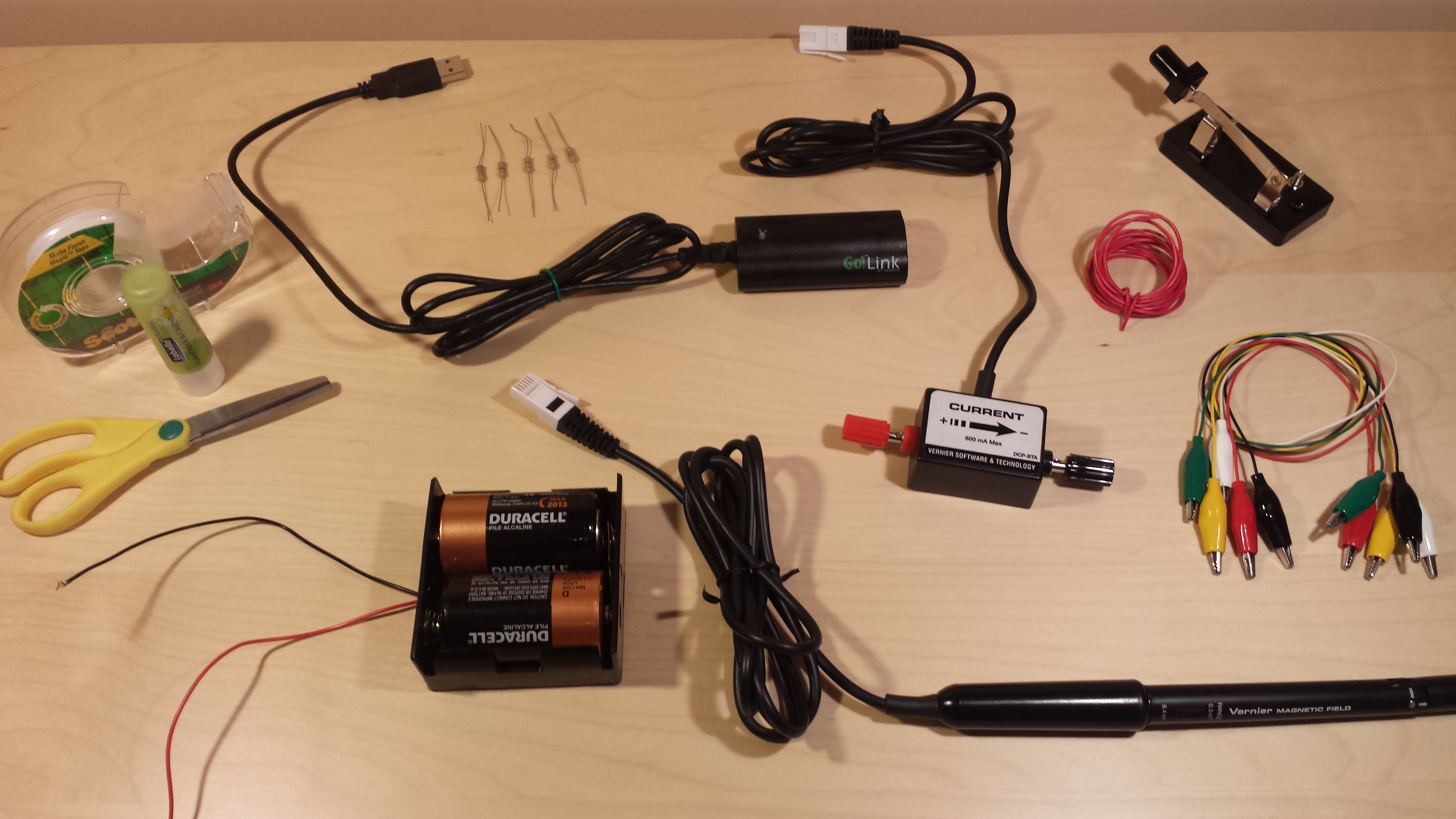
For this purpose, you will need the following items from the lab kit:
As in the previous experiments, you will also need a personal (desktop or laptop) computer with the Logger Pro software installed on it.
Before you begin, review the whole procedure to make sure you understand all the steps involved. Perform proper risk assessment and do not carry out with the experiment if you feel that the procedure, equipment, or material pose any safety issues. Remember that safety comes first, and you must always ensure the safety of yourself and any person at your location. If you have any questions or concern, please contact your tutor.
To prepare for the setup, first construct the solenoid. For this purpose, you need a relatively long cylindrical object (e.g. felt marker, lip balm, AA battery, etc.), which is slightly wider than the magnetic field sensor. Wrap the insulated copper wire tightly around the cylindrical object, making sure the windings are closely packed side-by-side with each other. Make a minimum of 20 turns around the cylinder. Then, without loosening the coiled wire, wrap it with clear tape to preserve the helical structure. Make sure to leave about an inch of wire extending on both sides of the solenoid. You may ask someone to help you in this process. After that, remove the cylindrical object and use a pair of scissors to expose about one centimetre of the insulation at both ends of the wire (see Video 4.1). Record the number of turns ($N$) and the length ($l$) of the solenoid.
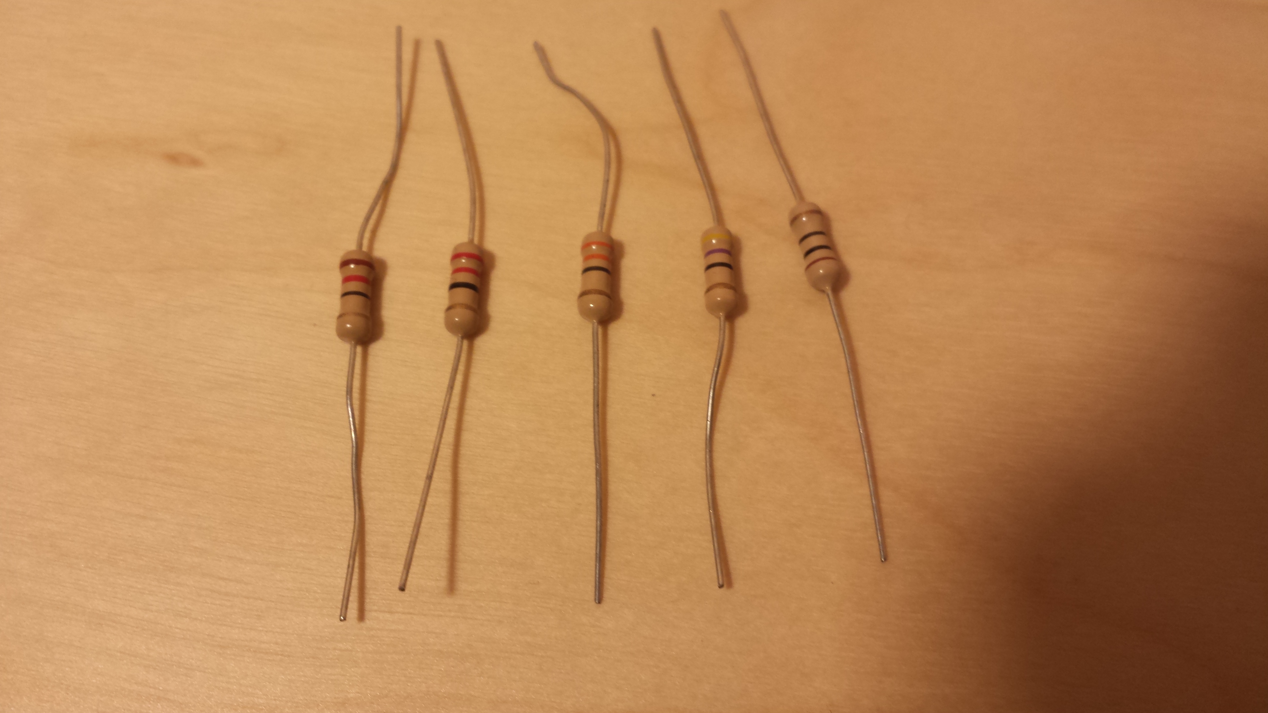
Choose a location away from permanent magnets or electric devices for your setup. Using connection cables, construct the circuit shown in Figure 4.2 and keep the switch open. For the resistor, you may want to start with the one whose value is closest to 50 $\Omega$. Since the circuit is still open, the reading displayed on the screen should be close to 0 A. If not, click on Experiment in the menu bar of the Logger Pro program, and select Zero... from the scroll down menu (see Video 4.1).
Note that a relatively large current may flow through the wire, especially when using a small-value resistor (such as $15\,\Omega$). Therefore, it is important to keep the switch open when you are not making measurements, so that the resistor and other circuit components do not overheat.
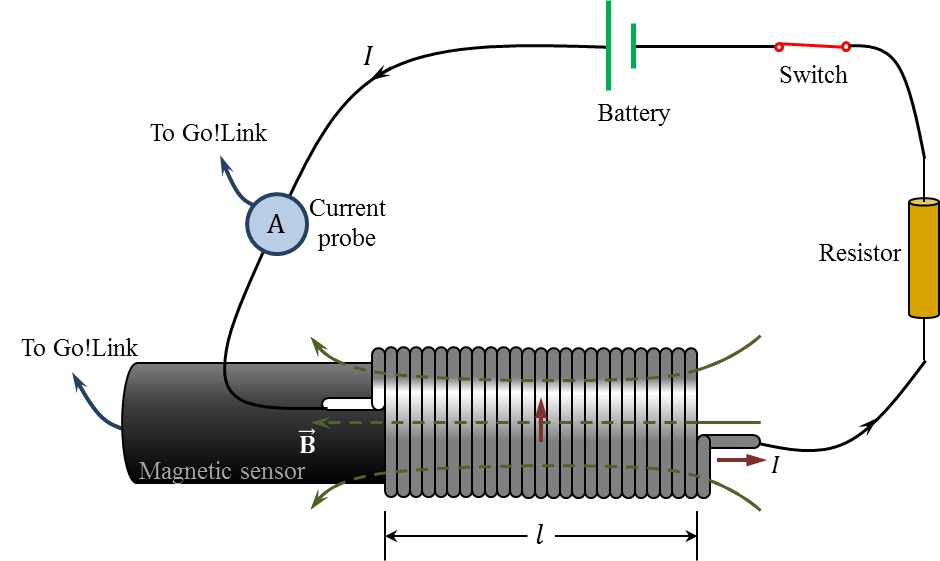
Push the magnetic field sensor inside the solenoid, as shown in Figure 4.3, until the sensor's tip is near midpoint. Disconnect the Current probe from Go!Link and connect the magnetic sensor instead. Note that this device is sensitive to the component of the magnetic field perpendicular to the sensor's tip. While the switch is still open, the sensor measures the Earth's magnetic field and possibly stray fields of electronic devices or permanent magnets in the vicinity. Therefore, such background field should be subtracted before closing the circuit. To do that, click on Experiment and select Zero... from the scroll down menu. The magnetic field reading will reset to zero. Also, set the sensitivity of the magnetic sensor to 0.3 mT on the device.
| Resistance $R\;(\Omega)$ |
Magnetic field $B\;(\text{mT})$ |
Current $I\;(\text{mA})$ |
Under Experiment, select Data Collection and set Duration to 20 s. Set Sampling Rate to 5 samples/second. Double-click in the graph window and deselect the Connect Points option. Also, under Axes Options, set the $y$ axis range from 0 to 0.15 mT.
To begin measuring, close the switch and click the green Collect button in the menu bar. Immediately begin pushing the magnetic sensor slowly through the solenoid from one end to the other. You should notice the magnetic field value increasing as you approach the solenoid's centre, then decreasing as you move closer to its end. After you have acquired all the data, you will have a set of data representing the magnetic field along the axis of the solenoid. Open the switch and save the Logger Pro file under a suitable name. Also, make sure to record the resistance ($R$) and current ($I$) values in Table 4.1.
Replace the resistor with one of lower value and repeat the procedure above. Continue the process until you have the magnetic field measurements for five different resistors. Do not forget to take a picture of your setup before disconnecting the circuit.
It is always important to keep the current under $0.2\,\text{A}$. Therefore, do not use any resistance less than $15\,\Omega$.